Introduction.
Whenever you need to power electronic stuff you need a constant voltage source. Circuits are specified to work for certain supply voltages, for example 5 volts plus or minus 10%. Circuits also like to draw different amounts of current depending on what they're doing, and that's bad for the power supply, who must struggle to keep a constant voltage output as the current demand from its load varies in time. So what happens if the power supply is suddenly required to provide more current for, let's say, a processor that's waking up from sleep and starting to do some work. Or a light or motor or something. It's bad. It can't keep the voltage constant. The voltage will drop for a very short time until the supply can sense that through its feedback loop and stabilize it. If it drops more than 10% or whatever the design margin is, the circuits might malfunction. When the circuit is done working and reduces its current demand, the opposite thing can happen and the supply voltage overshoots for a short amount of time. It it overshoots too high, the load circuit is fried.
So how can we fix this? Well, it's very simple in theory. Don't change the load current abruptly, so the supply has time to follow it and compensate for its change and mantain constant voltage output. The simplest way to do that is to throw a capacitor across the load. If the supply is slow to respond, the difference in current will come out of the capacitor instead of the supply, and the voltage variation will be much lower and everyone's happy.
Because the supply voltage is now constant, it means that various modules can't talk to each other through the supply wires (which would be bad), so they're being decoupled. That's why they're called (supply) decoupling capacitors.
My Problem.
People have always recommended using many small ceramic capacitor near integrated circuits and a few big electrolytic capacitors. The idea is that ceramics take care of the higher frequencies (rapid current variations), while the electrolytics deal with the lower ones. For a long time I've been wanting to actually test the effect of different kinds of capacitors on a power supply that's required to quickly switch between two values of current. Now I decided it was finally time to do that.
So I took a piece of copper-clad board and cut some trenches in the copper, isolating two big islands for the power and ground nodes where the action takes place, and some small islands for the other voltages. I soldered a good-old 7805 voltage regulator with capacitors on the input but not on the output, and a genric transistor that would suck a little bit less than 100mA when turned on by a signal generator. Some ports for the control signal, oscilloscope and raw power input, some very tight construction to avoid "parasitic inductance and capacitance", and it was ready. So here's the schematic:
 Notice the Schottky diode connected from base to collector á la 74LSxx. It diverts control current from the base to the collector whenever the collector voltage drops too low, preventing the transistor from saturating. That ensures fast switching.
So here is how the regulated voltage (that's supposed to be constant) looks like when current is switched on and off.
First, with no capacitor at all:
 Notice the almost 2V undershoot and 0.5V overshoot. That's... quite bad.
Here you can see a zoom-in on the negative spike:
 The oscilloscope samples at 100MHz, so that's 10ns between samples. The spike is just 3 samples. So it takes a bit of luck for its peak to coincide with the moment the sample is taken. Most of the time the peak falls before or after the sample, and the drop in voltage appears smaller than it actually is. You can see that in the first picture, where the drop is only around 1.7V, while in the second one I waited for a lucky sample and you can see the full 2V. Even after the spike is quickly dealt with, it takes a lot of time to compensate for the remaining half a volt. The same can be said about the 0.5V overshoot. I mean, 2 microseconds is a lot of time.
So I soldered in a 4.7 uF (microfarad) electrolytic capacitor, rated for 63V, and here is what I got:
 The red trace is the control signal. The current is drawn when the control signal is high. You can see an enormous improvement: the spike is gone, the drop is now only 100 mV (20 times less) and the overshoot is only 50 mV (10 times less). But it still takes about the same amount of time to stabilize. Anyway, while the first case would almost surely upset 74xx logic circuits, in this case they'd function allright. With no ceramic capacitors, mind you.
Then I did something horrible. I desoldered the capacitor, which was soldered close to the board, and put in a new one, holding it with my fingers. Its leads were about 1 inch long, which is supposed to be a big no-no: long leads means inductance, which slows down "reaction time" and prevents the capacitor from absorbing rapid current variations, leading to the voltage spike you saw in the first picture. But it was not the case:
 The 1 inch of wire did nothing noticeable, and that's in agreement with what the theory says. The oscilloscope samples at 100MHz and it's supposed to record signals at least as fast as 60MHz. How can you record a 60MHz signal on a 100MHz oscilloscope whose Nyquist frequency is only 50MHz? Figure it out, you most certainly can. So if, per Google, light travels 30cm in one nanosecond, it travels 3 meters in 10ns (that's 100MHz), which is much more than the 3 cm of the capacitor's leads. So they shouldn't matter that much.
Next I connected a 10uF, 16V tantalum capacitor. That's supposed to have a better frequency response than the usual electrolytics, as well as lower ESR (effective series resistance) - the stuff that limits how well it can filter spikes (think voltage drop over the ESR caused by the current you draw from the capacitor). It looks a little better:
 It's got a weird shape now. Oh well.
Here's a 22uF, 25V electrolytic with short leads (it's 20mV/div as before):
 Worse than the tantalum.
On all the pictures you can see the command signal feedthrough: when it goes down, the current is shut down and the voltage goes up temporarilly. But before the current is shut down and the voltage goes up, you can see a small downwards spike that's caused by the current injected from the command signal through parasitic capacitors. Because it's very fast, it gets through (it's coupled even through very small parasitics).
Next I connected a serious 100uF/50V capacitor with 1cm leads. You wouldn't normally want to use less than 100uF for decoupling a usual circuit. The improvement is clear:
 Now comes a 470uF/16V one, which is a little better, but not by much:
 Here is a 2200uF/10V:
 And a bigger 2200uF/35V:
 same, with 1 inch leads:
 You can begin to see that indeed, very fast spikes are filtered by the electrolytics worse than slower variations. That's what ceramics are for. Long lead lengths do add inductance (especially on the bigger capacitors where the leads are spaced farther apart -- it's area, not length that gives inductance) and spikes do get noticeably larger. You also couldn't see the effect of leads on the first capacitor (4.7u) because, well, look: 500mV per division sensitivity there versus 20mV per division here.
So if you want to get rid of those fast spikes, electrolytics are by no means totally useless as some might say, but a ceramic does a better job, especially if it's a low-inductance SMD (surface-mounted device) that has no leads.
Here is a 100nF ceramic disc capacitor, rated for 2kV (it's quite big for a ceramic, 1 cm in diameter), with ~1cm leads:
 Oops! :D It looks like the 7805 is oscillating when 100mA are pulled from it and a 100nF capacitor sits on its output. It's something that's mentioned in some datasheets, but not in all. Many voltage regulators are stable with low or high capacitive loads, but not with medium ones, and it also depends on load current. You can see some nice stability graphs in the TL431 datasheet from TI if I remember well.
The nasty thing is that it's a high-frequency oscillation, about 5MHz. It can go totally unnoticed if one doesn't have an oscilloscope, and low-frequency circuits would start acting in all sorts of weird ways. Plus, you don't want radio-frequency oscillations if you don't need them, because they could radiate and interfere with stuff. If they don't radiate directly from the circuit board, then signal and power wires on outside connectors are incredibly good antennas.
RF oscillation aside, a very important thing must be noted: no more fast (10-20 ns) spikes. You can see the fast voltage drop is slightly longer than with the electrolytic capacitors. That means better high-frequency filtering. But don't expect any low-frequency filtering from such a small capacitor - There's still a 1.2V drop.
At this point I soldered a 10nF SMD capacitor very close to the switching transistor. The oscillation is now much weaker, and you can see it's dying out - that's just my luck, the supply could have oscillated with 10nF just as well, and I would have had to find another value.
 Notice the slightly deeper 1.5V drop (smaller capacitor), but still no fast spikes. It actually works better that the 4.7 uF electrolytic, which is almost 500 times bigger :)
Here you can see the steep drop that's not nearly as steep as with no capacitor:
 The samples have been highlighted. It's at least 20 times longer.
Here is the 100nF ceramic added in parallel:
 Interestingly enough, there's no more oscillation. Well.
Here's the tantalum added:
 There's that strange shape again, and hey, there are spikes. They were always there, but just as with the 4.7u, we were looking on a 500mV/div scale, and now the filtering is so good we had to zoom in to 20mV/div and the spikes are now revealed. I have a suspicion that the spikes might be coupled inside the oscilloscope, which is also a signal generator and outputs the switching control signal. So I have to generate the signal somewhere else, but I already took all the screenshots for this article and packed all the stuff up before realising this now, so hell. I also really don't get why adding the tantalum speeds up the initial drop, it probably has something to do with the regulator, not the capacitor.
Anyway, here's a zoom-out with just the ceramic 10nF SMD capacitor:
 Now here's the same, with a pulse frequency 10 times lower:
 Damn it, it WAS oscillating :))
You can see two modes of oscillating, one high-frequency on turn-on and one low-frequency on turn-off. They both die out, but it's still not good for supplying a circuit.
Here are both ceramic capacitors:
 Just as with the faster pulse repetition rate, the high-frequency oscillation is gone; but the low-frequency one persists, and it's interesting to note it's slower when both caps are added.
The tantalum capacitor kills it for good, but gives that weird shape on turn-on:
 Here's a zoom-in of that:
 Here's the turn-on for the "normal" 100uF electrolytic:
 And the turn-off overshoot, complete with command feed-through spike:
 Until now I've been switching between 100mA of current and almost nothing. This is quite hard for the supply to deal with, hence the 2V drop when the current was turned on with no cap.
So I added another 50 ohm resistor directly on the output, so I would switch between 100 and 200mA.
Here it is, with the 10nF SMD capacitor:
 High-frequency oscillation with 100mA (strange, it didn't use to do that!), which ceases with 200mA (I was talking about stability graphs earlier). The effect might be caused by the fact that, as you let more current through a transistor, it becomes faster, and this happens inside the regulator chip.
The 100nF ceramic stops the oscillation:
 Here is the 10uF tantalum:
 And here is just the 10nF SMD (first graph in this sequence), with the repetition rate increased 10x. It does look similar:
 But it wasn't oscillating at 100mA before I connected the 50 ohm resistor! wtf? To answer, here's a graph after shutting down for 3 minutes to take a wee:
 Yes, it's the regulator chip temperature. You can actually watch the oscilloscope as the chip warms up (it does get pretty hot with 150mA average current, significantly hotter than with just 50) and suddenly the mild, damped oscillation turns into the ferm one I was puzzeled by. Then put your finger on the chip and it ceases. Or just blow hard. Fun.
I took out the SMD cap and here is what I got:
 and a zoom-in:
 The spike dropped from 2V to a little over 100mV, as a consequence of switching 100mA next to the existing 100 as opposed to "suddenly waking up" the regulator in the first case. Also compare the graphs taken with the tantalum cap. The peaks are smaller in this case also.This is normal, and almost no datasheet specifies transient performance ("load regulation") with the current step starting from zero, just because their numbers would be awful :)
Next I had to debunk a myth related to electrolytic capacitors. It seems that electrolytic caps get worse as they get older: their capacitance decreases, their ESR increases, their ability to filter decreases. So I took some capacitors I had lying around that I had taken out of some old monitors for the specific purpose of testing them. Now the time has come! :)
I should point out that said capacitors come from a scrapyard and have been rained on repeatedly. The other components on the PCB had their leads severely coroded. Compare with fresh off-the-shelf 10uF tantalum and 100uF electrolytic seen a few graphs above.
1000uF/35V:
 220uF/100V (higher voltage ratings supposedly have lower ESR -- good) :
 100uF/100V:
 330uF/250V (very big, 1 inch diameter, 1.5 inches long)
 This last one was quite big, very light, and different construction from others. Obviously filters less well, but that's acceptable, I guess it was designed to sit in the mains input circuit.
Well, there you go. Dirty old rained-on electrolytics filtering very well, quite better than new ones I might say. Of course, if they've leaked or grown internal pressure, scrap therm.
Now to try some film capacitors. These are big, but designed for high voltage, high current use, and I guess they also have less leakage than electrolytics.
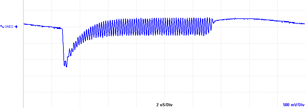
Here is a huge 1.5 inch, 3.3uF/400V from the same scrapyard:
 I guess the capacitor itself is resonating and I'm getting those damped sinusoids. I can't be sure until I pulse it in a passive circuit.
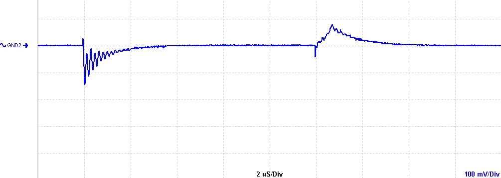
Here is a smaller 330nF/250V with its leads spaced about 1 inch apart:
 This also seems to shoot up when the current is increased, like the previous two caps, and unlike all others. I'll investigate this further some other time.
In conclusion: when in doubt, use a bigger capacitor.


No comments:
Post a Comment